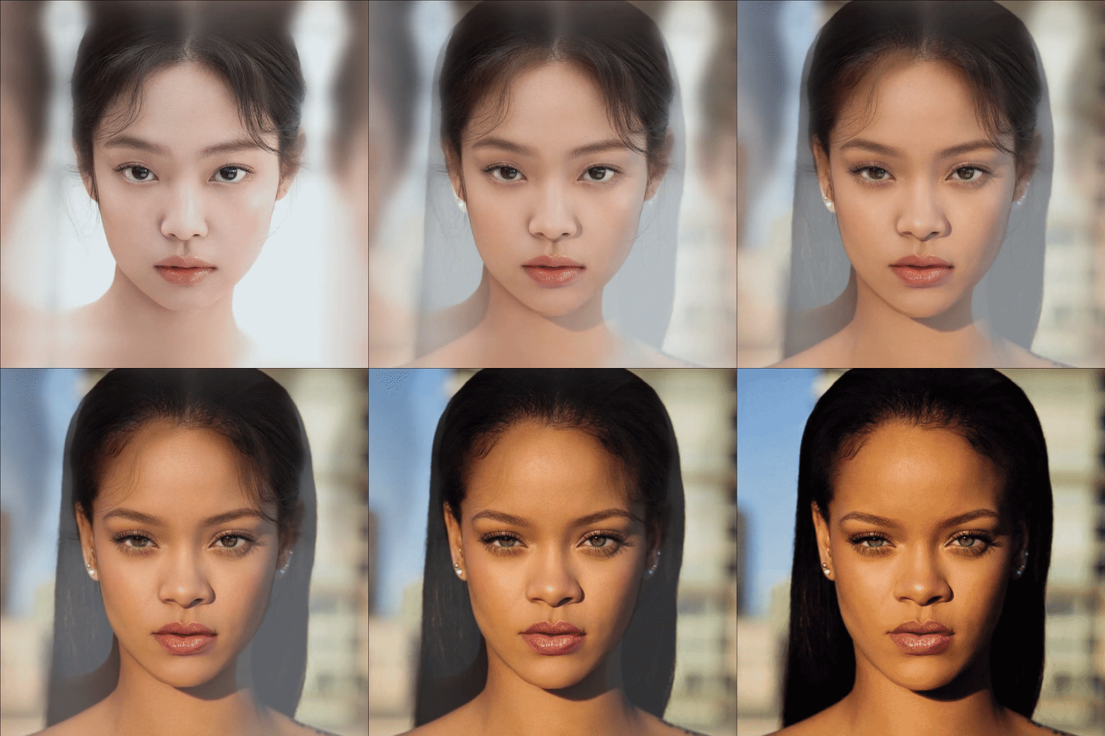
Face Morphing — A Step-by-Step Tutorial with Code

Morphing isn’t an unfamiliar technique for the audience — it played a large role in pop culture in cinemas throughout the 90s, made famous by Michael Jackson’s 1991 video for “Black or White”. The video features faces of different ethnicity and gender jamming to the song and morphing into each other, as a great reminder that we are all more alike than different.
This technique of morphing between two clips together was extended from morphing two still images, which is surprisingly not very hard to implement. In this article, I will walk through the face morphing procedures step by step, share the geometric intuition and my code implementation, hopefully, by the end of it, you will feel confident making your own version of face morphing!
First, let’s properly define the face morphing problem.
Problem statement
Input: Two images containing human faces (Image I₀ and Image I₁)
Output: A fluid transformation video transitioning from I₀ to I₁
Goal: The transition should be smooth and the intermediate frames should be as realistic as possible
An intuitive understanding
We can look at the target transformation video results as a sequence of frames. Given two input images I₀ and I₁, at each timestamp t between 0 and 1, every pixel (x, y) in the morphed frame can be interpolated as follows

When t equals 0, the morphed frame is exactly the Image I₀, when t equals 1, the morphed frame is exactly the Image I₁, and frame at t is the blending of two images at time t. This is called “cross-dissolve” in the film industry. Cross dissolve handles the photometric side of the problem, it balances out the coloration in the middle frames, but will inevitably leave the “ghosting” effects if the two faces aren’t perfectly aligned. See the examples below.

How can we address this issue? Clearly, we have to respect the geometric side of transformation. The ghosting effect is due to the misalignment of two faces, in particular, the misalignment of two sets of important facial features, such as eyes, nose, and mouth. Thus, to align the shape in between the output, we need to make sure that the important features can be consistently matched throughout the frames. If the point pairs were given, we can then calculate the new location of corresponding points in each morphed frames to create the average warped shape.
Now, we have a high-level idea of how morphing frames are calculated.
Given the corresponding features pairs, for each frame at time t:
1. Compute the intermediate shape by linear interpolation of each feature pair


2. Cross dissolve the color by interpolating two images

Let’s get started!
Detecting facial landmarks
In the algorithm above, we assume, the input correspondences at key feature points were given. A brute force way is to manually select correspondences, which is time-consuming and prone to human errors. Thus, we will need to find a way to smartly select important facial features correspondences.
Here we will utilize dlib to detect facial landmarks. Facial landmarks are used to localize the face in the image and detect the key facial structures on the face. Note that facial landmark detector from the dlib library is an implementation of the One Millisecond Face Alignment with an Ensemble of Regression Trees paper by Kazemi and Sullivan (2014).
The facial landmark detector will give us the estimated location of 68 (x, y) pair coordinates that represent salient regions of the face, including eye, eyebrows, nose, mouth, and jawline.

In addition to the 68 facial feature points, we also need to select some points outside of the face to include the background into the morphing frames. To make sure the background is included, we need to select at least 4 points (4 corners), here we will use 8 points (4 corners + 4 center points from each edge) to make the transition more smooth.
Warping Triangular Mesh
Now, how do we go from feature points to pixels? Enters the idea of the triangular mesh.
With the paired landmarks, we could define the same triangular mesh over two sets of points, which will give us triangle-to-triangle correspondences between two sets of facial features. Why would we use a triangle over other primitives? My understanding is that they are easy to work with and tessellate well so that we won’t end up with cracks in the mesh where two edges join.
Now we can break down the problem of defining the intermediate shape into many sub-problems — finding each intermediate triangles and then cross-dissolve the values into colors in the warped shape. Before we dive into how to assign the points into triangles, we will first show the feasibility of warping one triangle to another.
In fact, with only (x,y) coordinates initially, we are unable to capture the degree of freedom that represents such translation. In such cases, it is often convenient to work with homogenous coordinates that introduce a third w coordinate, where each (x, y) becomes (x, y, w). Since two points are equivalent iff x'/w' = x/w and y'/w'= y/w , we can just set w=1.
With this system, we can represent the 2D transformations with a matrix multiplication:

There are 6 unknows (a, b, c, d, e, f) in the matrix system above. If we vectorize transformation parameters, each pair of points (x, y) and (x’, y’) can determine two parameters.

Thus, using three pairs of vertices from the source and target triangles, we can solve the 6 unknowns with 6 equations, which uniquely identify the affine transformation matrix. With that, we can now solve any transformation of two triangles!

Intuitively, we want to calculate the transformation T that goes from source A to destination B such that T(A) = B, and then we can apply T to every pixel bounded by the triangle in A to find its corresponding coordinate in B. This process is called forward warping.
However, since T could be a matrix of floats from solving the matrix system, the calculated (x’,y’) coordinates could very likely land in between pixels. In this case, many source pixels can map to the same destination pixel, yet some destination pixels may not be covered.

To combat this, we use inverse warping instead, which solves the inverse of T. By solving for the inverse of T and applying the inverse affine transform to every coordinate in B, our resulting image can avoid “holes” (See figure below). When the pixel lands in between coordinates in the source triangle, we can then interpolate within the source neighbours.

By iterating through each pair of triangles, and calculating for each pixel in the source/ destination images, we are finally able to produce the morphed faces in the intermediate frames.
Let’s recap the morphing procedure with more details this time:
Given the corresponding features pairs, for each frame at time t:
- Compute the intermediate shape by linear interpolation of each pair
- For each triangle T in the intermediate shape

- Calculate the affine transforms from corresponding triangle A in I₀ and B in I₁ to T from the intermediate frame

- Warp A and B towards T using results from the previous step

- For each pixel in the triangle, find the corresponding points in A and B, and cross-dissolve the color by interpolating
Delaunay Triangulation
So far, we talked about choosing the facial landmarks (points) and generating the intermediate frames with triangular mesh. There’s only one link missing now — how can we organize the points into such triangles?
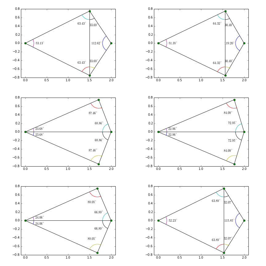
Given a set of points in a plane, triangulation refers to the subdivision of the plane into triangles, with the points as vertices. There is an exponential number of triangulations of a point set. The triangulation we will use for morphing is Delaunay triangulation — what makes Delaunay triangulation special?

Let α ( T) = ( α1, α2 ,.., αn) be the vector of angles in the triangulation T in increasing order. A triangulation T1 is “better” than T2 if the smallest angle of T1 is larger than the smallest angle of T2. With this, Delaunay triangulation is the “best” triangulation for maximizing the minimal angles, and they tend to avoid long skinny acute angles. Thus, we will use Delaunay triangulation in our implementation.

Here, I don’t intend to dwell on the Delaunay Triangulation algorithm, if you are interested, I found this book chapter very thorough.
In OpenCV, Delaunay Triangulation can be handled easily with Subdiv2D — the function creates an empty Delaunay subdivision where 2D points can be added using the function insert().

So far, we have introduced all the tools and techniques we will be using to implement the face morphing. Time to head over to the code! Check out the source code here: https://github.com/Azmarie/Face-Morphing.
Have fun morphing!
Key Features
- Detect and auto-align faces in images, This is optional for face morphing, though I find it helps to make the algorithm below more robust (early stopping if there’s no face found in the images)
- Generate corresponding features points between the two images using Dlib’s Facial Landmark Detection
- Calculate the triangular mesh with Delaunay Triangulation for each intermediate shape
- Warp the two input images towards the intermediate shape, perform cross-dissolve and obtain intermediate images each frame
More Results


Reference
- Wolberg, G. (1998). Image morphing: a survey. The visual computer, 14(8–9), 360–372
- Kazemi, V., & Sullivan, J. (2014). One millisecond face alignment with an ensemble of regression trees. In Proceedings of the IEEE conference on computer vision and pattern recognition (pp. 1867–1874).
- Schwarz, L. A. (2007). Non-rigid registration using free-form deformations. Technische Universität München. Retrieved from https://www.researchgate.net/publication/267946997_Non-rigid_Registration_Using_Free-form_Deformations
- Van Kreveld, M., Schwarzkopf, O., de Berg, M., & Overmars, M. (2000). Computational geometry algorithms and applications. Springer.
- Delaunay Triangulation. In Wikipedia. Retrieved from https://en.wikipedia.org/wiki/Delaunay_triangulation